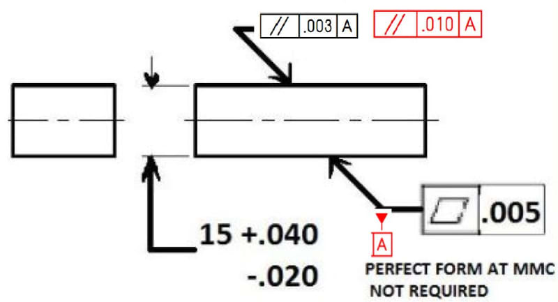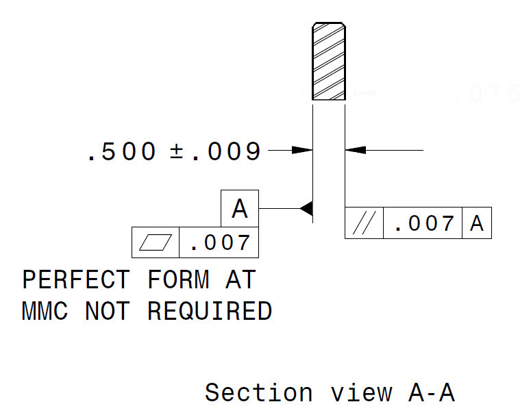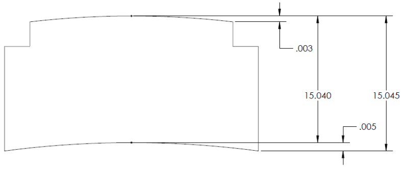

Feel free to come back with additional questions. If you have access to the ASME Y14.5 – 2009 standard I suggest you take a look at Figure 2-7 and Section 2.7.1. You should note that if the independency symbol (I) is applied then it is no longer required for your flatness tolerance to be smaller than you size tolerance. It is also for this reason that any tolerance for a form control must be less than the size tolerance as Rule #1 has an inherent flatness/straightness/circularity/cylindricty control built into it. It is only as your part departs towards LMC that any form error is permissible. 90 – 1.00 in size with no controls and the part is manufactured at 1.00 there can be no flatness error on the surface in question. For example, if you have a plate that is. Meaning that, at the maximum material condition of the part perfect form is required. As to whether or not you need it, I can’t answer as I’m not intimately familiar with your particular design.Īll of the form controls (flatness, straightness, circularity and cylindricity) as well as general tolerance of size are governed by Rule #1. You’ve hit upon one of the few ways that the Rule #1 (perfect form at MMC) can be overruled. The tabletop may be within flatness tolerance but would not be parallel to the floor. Think of a table with two missing legs at an angle to the floor. Parallelism uses a datum to control a surface while flatness does not. Table using the GD&T flatness Symbol Final Notes:įlatness is not the same as parallelism. (You would be rejecting tables that were good thicknesses and normally in spec if using GD&T) With flatness, you can allow the table to be flat without constraining the tabletop thickness very tight. If you want to make sure that a tabletop is perfectly flat, if you did not have a flatness callout, you would have to constrain the height of the table very tightly to make sure that the entire surface is straight. Commonly used on a fixture that must mate flush with another part without wobbling, but where orientation is not important. Usually, flatness is used to give a surface an even amount of wear or for sealing properly with a mating part. When you want to constrain the amount of waviness or variation in a surface without tightening the dimensional tolerance of said surface. This would be measuring parallelism instead as you are fixing the bottom of the part as a datum.įlatness is the 3D version of surface straightness – Instead of the tolerance zone between two lines the tolerance zone exists between two planes. Flatness cannot be measured by simply placing the part on a granite slab and running a height gauge or microheight over it. This is a 3D measurement so points must be measured across the length and width of the part to ensure the entire surface is in tolerance. Modern CMM’s are best for measuring the part as they can create virtual planes that the true surface profile can be compared to. You are trying making sure that any point along the surface does not go above or below the tolerance zone. Two Sets of Parallel Planes where the entire referenced surface must lie.įlatness is can be measured using a height gauge run across the surface of the part if only the reference feature is held parallel.

Flatness tolerance is always less than the dimensional tolerance associated with it. The flatness tolerance references two parallel planes (parallel to the surface that it is called out on) that define a zone where the entire reference surface must lie. It comes in useful if a feature is to be defined on a drawing that needs to be uniformly flat without tightening any other dimensions on the drawing. It is a common symbol that references how flat a surface is regardless of any other datums or features. This would make the first time assembly a bit quicker.Symbol: Relative to Datum: No MMC or LMC applicable: Yes – New in 2009 Drawing Callout: Description: The instructions are handily printed on the bag, although we feel Vango could improve on these by including a diagram referring to the name of each piece of kit. Lastly insert the bracer pole, which connects inside the awning to the main airbeams with velcro tabs, to increase tension in the roof.
#ASME Y14.5 2009 FLATNESS MANUAL#
Next blow up the airbeams (easy to inflate with the manual double handled pump included). We used webbing straps, which were thrown over the roof and pegged on the other side. Loosely pegging out the four corners, attach the awning to your camper either with the pre-attached 6mm kador strip (which fits straight onto a rail on your vehicle if you have one), or with webbing straps, velcro tabs or pole and clamps.

Expect the first time to take around half an hour, although after practice we easily managed to get this down to 10 minutes.

It can also be used with any campervans and even motorhomes.Īfter a few goes, setting up the Idris II is a doddle. The Vango Idris II Airbeam Awning is a freestanding drive away campervan awning.


 0 kommentar(er)
